banner
II – METHOD AND EXPERIMENTAL SETUP

In explaining this study, a signal transmitter device that produces homogeneous and uniform electromagnetic waves has been used. The device frequency is assumed to be constant and equal to f0.
According to this frequency value, the wavelength of the sinusoidal signals produced by the device will satisfy the relation c = f0 · λ0.
Therefore, the values f0 and λ0 are accepted as the fundamental factory characteristics of the device. It is assumed that all signal transmission processes discussed in this study are carried out with these constant-frequency signal generators. One of these devices is placed on an aircraft, while the others are placed on signal towers.

Figure 1 – Device used in the study.
Information note:
All figures used in this article are created from frames taken from the related animations. The star symbol (★) in figure descriptions indicates that the relevant figure has a viewable animation.
While reading the article, you can also watch these animations simultaneously.
Experimental Setup:
In the First Section of the explanation of the subject:
As seen in Figure 2 below, there is a tower located at position O in the center, and two side towers at positions A and B on both sides.

Figure 2 – The tower at position O in the center sends signals to towers A and B.
In Figure 3, there is an aircraft passing over position O, and similarly there are towers at positions A and B.

Figure 3 – As the aircraft passes over position O, it begins sending signals to towers A and B.
The distances of the side towers A and B from position O are equal to each other. In the study, signals were first sent from the middle tower to the side towers A and B, then signals were sent from the aircraft to towers A and B, and the two situations were compared; wavelength changes and signal speeds related to Doppler Shift were examined through these comparisons.
In the Second Section of the explanation of the subject:
As seen in Figure 4, this time signals were sent from the side towers A and B to the aircraft in the middle, and again the wavelength change and signal speeds arising due to Doppler Shift were examined.
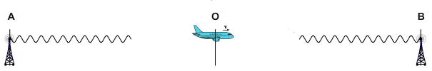
Figure 4 – As the aircraft passes over position O, towers A and B begin sending signals.
In order to clearly observe the formation of Doppler Shift and how signal speeds differ according to the source and target reference frames, the motion of the towers and the aircraft was chosen along the same line. Thus, it has been shown more clearly which physical quantities cause the changes in wavelength and wave speed.
III – SUBJECT EXPLANATION AND DEVELOPMENT OF THE EVENT (First Section)
1) A Signal Is Sent from the Middle Tower
The tower at position O in the center sends a signal to towers A and B, which are at equal distances from it.
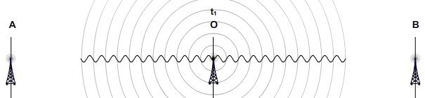
Figure 5 – The middle tower is sending signals to the side towers.
Development of the event:
- − The tower begins sending signals at time t1.
- − The signals moving in both directions reach the side towers at time t2.
- − Signal travel time:
t = t2
− t1
Distances traveled by the signals going to the right and left: since the signal speed is “c”:
AO = BO = c · t
- − Expressing the traveled distances in terms of wavelength:
The source and target towers are stationary relative to each other. Therefore, there is no change in the wavelength of the signal, and the constant wavelength, which is the production value of the device, remains valid.
Therefore, the traveled distance:
AO = BO = n · λ0
The value of n:
n = c · t / λ0
Since the towers are stationary relative to each other, the wavelength of the signal will not change here.
Figure 6 below shows the arrival moment of the signals and the related mathematical equations.
flash 1
2) Sending Signals from the Aircraft to the Towers
At time t1, the aircraft passing through position O begins sending signals to the towers on both sides. The speed of the aircraft is taken as “v”.

Figure 7 – The aircraft is sending signals to the side towers.
Due to the motion of the aircraft, it is clearly seen that the wavelengths of the emitted signals change. In the animated version of the figure, this situation can be observed clearly without the need for any explanation.
- − The wavelengths of the signals going toward tower A behind the aircraft are elongated and are denoted by λ1.
- − The wavelength of the signals going toward tower B in front of the aircraft is shortened and is denoted by λ2.
Summary of the flow of events:
At time
t1, signal emission begins while the aircraft is at position
O.
- − Since the signals start from position O, they arrive at towers A
and B, which are at equal distances from point O, at the same moment t2.
- − Travel time of the signals:
t = t2
− t1
- − At the initial moment of the event, t1, the aircraft is at position O.
During the time until the signals reach the towers, the aircraft moves with speed v and arrives at position C at time t2.
Distance traveled by the aircraft during this time:
CO = v · t
- − The aircraft emits signals in both directions with the same frequency. Therefore, the numbers of wave sequences formed in both directions are equal. This number is shown in the figure by “n”.
Showing the distances traveled by the signals sent to the towers in the aircraft’s own reference frame:
Signal going to the left (toward tower A):
Tower A is moving away from the aircraft with speed v. In this case, the distance traveled by the signal going to tower A:
In terms of speed and time: AC = c · t + v · t = (c+v)
· t
In terms of wavelength: AC = n · λ1
Signal going to the right (toward tower B):
Tower B is approaching the aircraft with speed v. In this case, the distance traveled by the signal going to tower B:
In terms of speed and time:
 BC = c · t
− v · t = (c–v) · t
BC = c · t
− v · t = (c–v) · t
In terms of wavelength:
BC = n · λ2
In the figure below, the moment the signals arrive at towers A
and B, together with the
related mathematical equations, is shown.
At this point, we can clearly see the
fundamental error made in Electromagnetic Theory.
According to Electromagnetic Theory, the speed of electromagnetic
signals sent from a source must always be “c”
regardless of which reference frame is considered. According to the
ground reference frame and the reference frames of the side towers A and B, it is clearly seen in the figure,
without dispute, that the speed of the signals is “c”.
In contrast, when we move to the
reference frame of the aircraft, the physical picture changes
completely. In the aircraft’s reference frame, the speed of the
signals going to tower A becomes "(c + v)"
and the speed of the signals going to tower B becomes "(c - v)".
Considering that the arrival time of the signals at towers A and B is t = t2 − t1, the signal
speeds in the aircraft’s reference frame are easily calculated:
According to the aircraft’s reference frame:
Speed of the signals going to tower A:

Speed of the signals going to tower B:

thus becomes.
Therefore, the fact that the speeds of the signals sent by the
aircraft are c ± v instead of c creates a clear contradiction with electromagnetic theory,
which claims that the speed of light must be constant in all reference
frames. This result shows that the theory does not correctly
reflect reality at a very critical point.
flash 2
Another important finding revealed by the graph is the following:
All of the signals going to the left have the same wavelength
(λ1).
Similarly, all of the signals going to the right also have the
wavelength λ2.
These changes in wavelength occurred
independently of the
characteristic properties of the device emitting the signal
and at the moment of signal
emission.
This process can be clearly observed in the animated version of the
figure.
The factory settings of the device theoretically satisfy the relation

although this relation is satisfied, thinking that the wavelengths of
the signals emitted by the device
will always be λ0 does not reflect
the real physical situation.
Here, λ0 is only a
reference wavelength.
The physical quantity that determines the change in wavelength is the
relative speed “v” between the Source Object
and the Target Object.

Doppler Shift Equation
As seen in the Doppler Shift equation, the change in wavelength
occurs by applying a ratio determined by v
to λ0.
Therefore, λ0 is the fundamental
reference quantity on which the change takes place.
The fact that the relative speed between the Source Object and the
Target Object can physically take any
value
means that the signal wavelengths produced by the device
can vary in an infinite variety of
ways.
The device sends signals not only to the towers, but also
simultaneously to many objects moving in different directions and at
different speeds relative to itself.
Since these signals are produced by the same device, their frequencies
remain the same, but depending on the Source–Target relative speeds,
their wavelengths take different
values.
When the shapes formed together by the signals in the sky in the figure
are examined, it is seen that homogeneous
wave sequences are formed on both sides.
This is an expected result, since the device operates at a constant
frequency and the aircraft moves in uniform linear motion.
However, this appearance also reveals a very important physical fact:
“In Doppler Shift, the change in
wavelength occurs during the emission of the signal.”
Considering that the change in the signal wavelength takes place at the
moment the signals are emitted, it becomes easier to understand how
extraordinary the physical mechanism we are facing really is.
3- Comparison
Here in Figure 9, Figures 6 and 8 are presented one below the other so
that they can be seen together for comparison purposes.
 • In the upper part,
the situation in which the aircraft
sends signals to the towers at positions
A and
B (Figure 8),
• In the upper part,
the situation in which the aircraft
sends signals to the towers at positions
A and
B (Figure 8),
• In the lower part, the situation
in which the tower at the central
position O
sends signals to the side towers (Figure 6) is shown.
flash
Summary of the flow of events in Figure 9:
- − At time t1, the tower at position O and the aircraft are aligned, and the signal emission begins exactly at this moment.
- − At time t2, the signals reach the towers at positions A and B, and at the same moment t2, the aircraft has arrived at position C.
- − Since both the aircraft and the central tower use the same type of signal generator, during the interval t = t2 − t1, both sources emit the same number of waves in both directions, namely “n” waves.
- − For the signals sent from the central tower to the side towers, since the towers are stationary relative to each other, the wavelength of these signals does not change and remains λ0 in both directions.
In contrast, for the signals sent from the aircraft, since the aircraft and the towers are in relative motion,
• the wavelength of the signals going to the left becomes longer → λ1
• the wavelength of the signals going to the right becomes shorter → λ2
and thus changes.
As can be clearly seen in the figure,
λ1 > λ0
> λ2
gives the ordering.
Calculation of signal speeds in the aircraft’s reference frame
Using the quantities given in the figure, the speeds of the signals sent by the aircraft to towers A and B in the aircraft’s reference frame can be calculated quite simply.
Signal going toward tower A:
Since the aircraft and tower A are moving away from each other, the distance traveled by the signal is
AC = (c + v) · t
Therefore, the speed of the signal going to tower A according to the aircraft’s reference frame is:
Signal going toward tower B:
Since the aircraft and tower B are approaching each other, the distance traveled by the signal is:
BC = (c − v) · t
Therefore, the speed of the signal going to tower B according to the aircraft’s reference frame is:
Fundamental result:
These results clearly and indisputably show that in the aircraft’s reference frame
the speed of the signals going to tower A on the left is (c + v),
and the speed of the signals going to tower B on the right is (c − v).
This finding contradicts the fundamental assumption of electromagnetic theory that “the speed of light must always be c in all reference systems,” and shows that this assumption does not fully reflect physical reality.
IV – MATHEMATICAL EQUATIONS
DERIVATION OF THE DOPPLER SHIFT EQUATIONS
That the quantities obtained from the figures correctly represent the
true behavior of nature can be clearly understood from the following
fundamental fact:
The equation that gives the change in wavelength in Doppler Shift can
be derived directly from the geometric and temporal relations in the
figures, without the need for any additional information.
Below, it is shown how the Doppler Shift equations are obtained by
using the information provided in Figure 9.
Arrival time of the signals:
The arrival time of the signals emitted from the aircraft to the towers
at positions A
and B:
t = t2 − t1
t1 : moment of signal emission
t2 : moment when the signal reaches the towers
During the time interval t, the aircraft
moves with speed v from position O
to position C.
Obtaining the wavelength of the signals sent from the aircraft to
tower A on the left:
The aircraft and tower A
are moving away from each other.

Obtaining the wavelength of the signals sent from the aircraft to
tower B on the right:
The aircraft and tower B are
moving toward each other.

VI – SHOWING SIGNAL SPEEDS WITH WAVE MECHANICS
In the aircraft’s reference frame, even if the speed of the signal it sends differs from the value c, Wave Mechanics is still completely preserved in this case. It has been clearly shown here that the signal speeds (c+v) and (c−v), obtained according to the aircraft’s reference frame, are in full agreement with Wave Mechanics.
According to Wave Mechanics, the speed of a wave is:
Wave speed = Wavelength x Frequency
as follows.
In the aircraft’s reference frame, it was obtained in the previous sections that the speed of the signal sent to the left (toward tower A) is (c+v), and the speed of the signal sent to the right (toward tower B) is (c−v). The speed of the signals sent from the central tower is c, and the equality c
= f0 · λ0 is satisfied.
1) Wave Mechanics for the signals sent from the aircraft to tower A:
We use the Doppler Shift equation numbered [1], obtained in the fourth section (the aircraft and tower A are moving away from each other)

This result shows that the signal going to tower A moves with its frequency, wavelength, and speed in a manner consistent with Wave Mechanics.
2) Wave Mechanics for the signals sent from the aircraft to tower B
The same procedure is applied here as well. Using the Doppler Shift equation numbered [2], previously obtained on page 10 (the tower and the aircraft are approaching each other), the result is reached.

3) Results
As can be clearly seen in the equations numbered [3] and [4] that we have obtained, if the wavelength of the signal changes at the moment of emission, the emission speed of the signal differs from the constant “c”. It should be particularly emphasized here that this speed value is the speed according to the reference frame of the Source Object emitting the signal.
4) According to the towers, what are the frequencies of the signals coming to them from the aircraft?
According to the reference frame of the Target Object to which the signal will arrive, the speed of a signal coming to it is always constant and equal to c.
The wavelength of the signal arriving at Tower A is λ1,
and the signal has arrived at it with speed c.
Therefore, the frequency of the arriving signal is

.
The wavelength of the signal arriving at Tower B is λ2,
and the signal has arrived at it with speed c.
Therefore, the frequency of the arriving signal is

.
VII – THE PATH TOWARD THE FUTURE OF PHYSICS
At this stage, I would like to talk about a subject that directly
concerns the future of physics and that will guide the development of
physics in the years to come. Under normal circumstances, such
considerations are presented at the end of a study; however, I felt the
need to make an exception here. Because in order to understand the
continuation of the subject, we must first demonstrate the existence of
a very special and extraordinary situation.
Let us imagine that we observe a galaxy located millions or even
billions of light-years away. In such observations, the Doppler Shift
always clearly reveals itself. But how is this possible?
As shown in the previous sections, in Doppler Shift the change in
wavelength occurs during the emission of the signal. The real meaning
of this phenomenon is the following:
A star in that distant galaxy, as if it knew the speed of the Earth
relative to itself, emits its light by adjusting the wavelength of the
emitted light so that it satisfies the Doppler equation.
The electromagnetic signal leaving the star toward the Earth begins its
journey—lasting millions or billions of years—with a modified
wavelength. When the signal reaches the Earth, we measure its wavelength
(or frequency) and, by using the Doppler Shift equation, calculate
whether the star or galaxy is moving away from us or approaching us.
The critical point here is the following:
The distance between the star and the Earth has no importance in this
mechanism.
Even if the galaxy were a billion times a billion light-years away from
us, the Doppler Shift would still occur in exactly the same way.
For Doppler Shift to occur, there must exist in nature a mechanical
infrastructure that determines the wavelength of the signal at the
moment of emission and that physically produces the mathematics of
signal speeds (c+v) and (c−v). If the universe did not possess such a
mechanical infrastructure, the phenomenon called Doppler Shift could
not occur at all.
At present, there is no clear
information in physics about what this mechanical infrastructure
actually is.
Existing theoretical frameworks explain how Doppler Shift is
calculated; however, they cannot provide a satisfactory explanation of
why and how this mechanism exists.
The results obtained in this study —namely that the change in wavelength
occurs at the moment the signal is emitted and that the signal speed
according to the reference frame of the Source Object may differ from
c— add a new depth to the subject of Doppler Shift. However, this study
also does not reveal what the “mechanical infrastructure” actually is;
it only points to its existence in a much stronger and more direct
manner.
Therefore, a great question stands before the science of
physics—one that will shape future research:
What is the true nature of the
hidden mechanism of the universe that makes Doppler Shift possible?
The answer to this question will be one of the fundamental
building blocks determining the future of physics.
VIII – SUBJECT EXPLANATION AND DEVELOPMENT OF THE EVENT (Second Part)
THE TOWERS ON THE SIDES SEND SIGNALS TO THE AIRCRAFT
In the first part of the explanation, while demonstrating the formation of the Doppler Shift, the simplest scenario was chosen: the signals were emitted from the aircraft and sent to the towers located on the sides, which were stationary. Since the speeds of the signals going to the towers are c according to the Earth’s reference frame, there is no physically contradictory situation in this setup. Thus, the structure of the event can easily demonstrate the formation of the Doppler Shift, that the signal speeds differ from c according to the aircraft’s reference frame, and their relationship with wave mechanics without any forced assumptions. The reason why the wavelength of the signal changes also becomes quite clear when the figures are carefully examined.
In this second part, the sequence of events is examined from a different perspective. Here, the towers on the sides send signals to the aircraft in the center. At the initial moment of the event, while the aircraft is at position O, the towers begin to send signals.
Since the towers and the aircraft are moving relative to each other, Doppler Shift will inevitably occur in this case as well. The fundamental question that must be answered here is the following:
Where and how does the change in wavelength occur, and what are the speeds of the signals sent by the towers to the aircraft?
1) Incorrect assumption:
Let us assume that the signals from the towers are emitted in all directions with the speed “c” (Figure 9). When these signals reach the aircraft moving with speed “v”, we might think that an effect in the form of (c+v) and (c−v) would occur depending on the direction of motion of the aircraft. At first glance this may seem reasonable, but this assumption is not compatible with physical reality.
Because if this assumption were accepted as correct, it would imply that the speed of the signals arriving at the aircraft is not “c” according to the aircraft’s reference frame. In that case, in the aircraft’s reference frame, the speed of the signals coming from the front would be (c+v), and the speed of the signals coming from behind would be (c−v). This would lead to the following physical contradiction: the aircraft would experience a decrease in energy for the signals coming from behind, as indicated by the expression (c−v), and an increase in energy for the signals coming from the front, as indicated by the expression (c+v).
However, in Doppler Shift the situation is exactly the opposite. In Doppler Shift, (c−v) represents an increase in energy (the wavelength becomes shorter), whereas (c+v) represents a decrease in energy (the wavelength becomes longer). Therefore, this assumption is not compatible with nature and cannot explain physical reality.

Figure 10 – The towers on the sides are sending signals to the aircraft at speed c.
2) Correct Assumption:
If we produce a mathematical solution by accepting that, according to the aircraft’s reference frame, the speed of the signals coming toward it is c, it is seen that the correct result immediately appears. However, this approach has a natural consequence:
According to the reference frame of tower A on the left, the speed of the signals it sends to the aircraft must be (c+v).
According to the reference frame of tower B on the right, the speed of the signals it sends to the aircraft must be (c−v). (Figure 11)
In the first section, we had found that in the aircraft’s reference frame the speeds of the signals it sends to the towers are (c+v) and (c−v). Could such a situation also be valid here?

Figure 11 – The tower on the left sends a signal to the aircraft at speed (c+v), while the tower on the right sends a signal at speed (c−v).
Now let us see that this solution method is correct.
Even if we cannot explain for the moment why the speeds of the signals sent by the towers to the aircraft change (I am referring to that mysterious mechanical infrastructure of the universe), there is a simple and effective method to prove that this solution path is correct. For this, it is sufficient to appeal to the Galilean Principle of Relativity. While this principle easily shows that this solution path is correct, it also leaves no room for debate.
Galilean Principle of Relativity: The
fundamental laws of physics are the same in all reference frames moving at constant velocity relative to one another.
The Galilean Principle of Relativity states that the laws of physics apply in the same way in all reference systems moving without acceleration (at constant speed). It points to many logical conclusions that we can make use of in physics. By making use of these logical conclusions, it is often possible to arrive at a solid and correct conceptual integrity. We will follow the same method here. Below are given some important conclusions prepared by making use of this principle and directly related to our subject.
1) The distinction between moving object and stationary object is not absolute.
Within the logic of physics, if two objects are in motion relative to each other, there is no physical answer to the question “which one is moving and which one is stationary.” According to a specially chosen reference frame, we may assume either of these two objects to be at rest. Such a choice will not create any difference in the physical processes between the two objects.
2) Who sends the signal does not change the physical result.
Because of the previous logic, in our example of the tower and the aircraft, it should not matter which one sends the signal. The change in the wavelength of the signal depends on the relative speed between the Source Object and the Target Object, but it does not depend on which object sends the signal. Since the wavelength of the signal sent by the aircraft to tower A is λ1, the wavelength of the signal sent by tower A to the aircraft will again be λ1. Similarly, since the wavelength of the signal going from the aircraft to tower B is λ2, the wavelength of the signal that tower B sends to the aircraft will also be λ2.
3) According to an object, the “speed of the incoming signal” is universally c.
According to the reference frames of towers A and B, since the speed of the signal arriving at them is constant and equal to c, the speed of the signal arriving at the aircraft according to the aircraft’s reference frame must also be c.
Is this condition satisfied? It can be seen from Figure 11 that this condition is satisfied.
According to the aircraft, the speed of the signal coming from tower A is: c = (c+v)−v
According to the aircraft, the speed of the signal coming from tower B is: c = (c−v)+v
4) The mutual arrival times of the signals must be simultaneous.
Since the signals sent by the aircraft to towers A and B reach these towers t
in time and simultaneously , the signals sent by the towers to the aircraft must also reach the aircraft t in time and simultaneously.
5) The speeds of the signals sent by the towers must be (c ± v).
According to the aircraft’s reference frame, since the speed of the signal it sends to tower A is c1 = c
+ v = f0 · λ1,
according to the reference frame of tower A, the speed of the signal it sends to the aircraft must be c1
= c + v = f0 · λ1.
A similar situation exists for tower B. According to the reference frame of tower B, the speed of the signal it sends to the aircraft will be c2
= c − v = f0 · λ2.
I believe that these examples are sufficient to demonstrate the logical consistency provided by the Galilean Principle of Relativity. The way for these logical results to appear correctly in the figures and animations is also clear: the figure must be constructed in such a way that it satisfies all the conditions stated above, and the mathematical arrangements must be made accordingly.
There is only one solution path that satisfies all the conditions completely:
The signals emitted from tower A must be sent to the aircraft with speed (c+v), while the signals emitted from tower B must be sent with speed (c−v).
The following figures show the two situations.

Figure 12 – The aircraft sends signals to the towers with speeds (c+v) and (c−v) .

Figure 13 – The towers send signals to the aircraft with speeds (c+v) and (c−v)
.
In Figure 14 below, the arrival moment of the signals is shown comparatively.
In the upper part of the figure the signals are sent from the aircraft; in the lower part the signals are sent from the side towers.
In both cases the signals have reached their targets. Figure
14 satisfies all the conditions required by the Galilean Principle of Relativity completely.
flash 4
When the data obtained from the figure are examined, it is seen that
the same mathematical equations are valid in both setups.
Thus, the Second Part, which is normally truly difficult to explain, is
explained in an easy way by using the Galilean Principle of Relativity,
moreover without needing any additional mathematical derivation. If I
had tried to explain the second part in the normal way, I would have
had to make an explanation consisting of hundreds of pages, and many of
the things I explained would have been lost among theoretical
predictions and uncertainties. The Galilean Principle of Relativity is
truly a very powerful principle.
IX – FINDINGS AND CONCLUSIONS
This study has revealed extremely important findings that directly
concern the cornerstones of physical theory. The results obtained are
summarized below in itemized form:
1. The physical meaning of the
constant of the speed of light is incorrectly known.
The most fundamental finding of this study is the following:
The constant of the speed of light c
represents the speed of the signal coming toward an object according to
that object’s reference frame.
For all objects, the speed of the signal coming toward them is constant
and equal to c.
2. According to the Source Object, the
emission speed of the signal is not constant.
In the Source Object’s own reference frame, the speed of a signal it
emits can take any value depending on which Target Object the signal is
going to. The speed of the signal is determined in the form of (c ± v)
in relation to the relative speed between the Source Object and the
Target Object. This speed value is also compatible with Wave
Mechanics.
3. The speeds of signals emitted
simultaneously from the Source Object are often different from one
another.
Let us consider a star as a Source Object. The star sends light signals
simultaneously to an almost infinite number of objects located nearby
or very far around it. Nearly all of these objects are moving with
different speeds and in different directions relative to the star.
Therefore, according to the reference frame of the Source Object, that
is, the star, the speeds of the signals emitted simultaneously but
going to different target objects will be different from one another.
Therefore, it is not correct to assume that the signals emitted simultaneously from the Source Object propagate as “the surface of a sphere expanding in space with speed c”. Such a model ignores the fact that, according to the Source Object, signal speeds can actually take different values such as (c+v),
(c−v), and therefore it has lost its validity.
4. The wavelength change in Doppler Shift occurs at the Source Object and at the moment of emission.
The amount of change in wavelength is determined by the relative velocity between the Target Object and the Source Object.
As a prediction, I would like to state here that “during the Doppler Shift process, the Source Object plays a passive role, merely producing and emitting the signal; whereas the Target Object plays an active role in determining the change in wavelength.”
5. At the moment a signal is emitted, the Target Object toward which it will travel is physically determined.
When the signal reaches its destination, its journey ends. Electromagnetic radiation is always an interaction occurring from one object to another; therefore it is not possible for a signal to be emitted without there being a target object toward which it will travel.
6. These findings clearly show that there is a fundamental deficiency/error in Electromagnetic Theory.
Current Electromagnetic Theory accepts only the constant value c for signal speeds and does not include the (c+v) and (c−v)
mathematics that we have outlined here. Electromagnetic Theory needs to be reorganized so as to incorporate the mathematics of (c+v) and (c−v).
7. When this adjustment is made, the Special Theory of Relativity will no longer be necessary.
When Electromagnetic Theory fully adopts the mathematics of (c+v) and (c−v), it will reach a state in which it can correctly express the electromagnetic interaction between objects moving relative to one another.
Since such a theoretical structure will already contain within itself all the physical phenomena that the Special Theory of Relativity attempts to explain, there will no longer be a need for a separate theory such as the Special Theory of Relativity.
8) Alice Law is the Electromagnetic Theory that uses the mathematics of (c+v) (c−v).
Since 2001 — that is, for almost 25 years — I have been working on the mathematics of (c+v)
and (c−v). All the studies I have prepared have been published under the name Alice Law. In the early years I evaluated Alice Law — that is, the mathematics of (c+v)
(c−v) — on the basis of an alternative relativity theory. However, over time I realized that this mathematics actually belongs to Electromagnetic Theory. Therefore today I can confidently say the following:
Alice Law is the Electromagnetic Theory that uses the mathematics of (c+v) (c−v).
Like the Theory of Relativity, Alice Law also points to many predictions and results. For example:
• In Alice Law there are Time Shift and Length Shift,
• In the Special Theory of Relativity there are Time Dilation and Length Contraction.
What I am trying to explain here is the following:
If you measure that time slows down somewhere, if you observe a change in the dimensions of an object, the reason for this is the existence of Alice Law.
It is not a correct method to approach Alice Law using the concepts of the Theory of Relativity.
It should also be remembered that there are important structural differences between the predictions of the two theories.
You can access all my studies regarding the predictions and results of Alice Law on my website aliceinphysics.com.
9) The path to the physics of the future.
As Electromagnetic Theory progresses on the basis of the mathematics of (c+v) and (c−v), the true physical meaning of the constant speed of light c will be better understood, and this will open the way to discovering the mysterious mechanical
infrastructure of the universe that gives rise to this mathematics.
X – REFERENCES
[1] Einstein, A. (1991). Relativity Theory
(G. Aktaş, Trans.). İstanbul, Türkiye: Say Yayınları.
(Original work published as Relativity: The Special and the General Theory)
[2] Ministry of National Education. (1996). Physics I for High Schools
(Publication No. 553; Textbooks Series No. 168). Ankara, Türkiye: Gaye Matbaacılık.
[3] Erim, H. (2017). Alice Law – Transition to (c+v) (c–v) Mathematics in Electromagnetic Theory
(Trans. M. H. Kaya; Redaction Y. Özmenekşe). İstanbul, Türkiye: Cinius Publishing.
Online publication:
https://www.aliceinphysics.com/publications/alice_law_8/en/index.html
[4] Erim, H. (2017). Alice Law – Transition to (c+v) (c–v) Mathematics in Electromagnetic Theory.
İstanbul, Türkiye: Cinius Publishing.
Online publication:
https://www.aliceinphysics.com/publications/alice_law_8/en/index.html
[5] Erim, H. (2025). Correction of the Major Error in Electromagnetic Theory and Transition to the Alice Law.
Zenodo:
https://zenodo.org/records/17667009
Online publications:
Turkish:
https://www.aliceinphysics.com/publications/alice_law_8/tr/part_61.html
English:
https://www.aliceinphysics.com/publications/alice_law_8/en/part_61.html
[6] Erim, H. (2025). Alice Law – Version 9 Physics Program [Software].
The program supports Turkish, English, Russian and Spanish languages.
Download address:
English Page:
https://www.aliceinphysics.com/download/download_en.html
link


