I will explain the hypotheses
on which Alice Law rests by constructing an event that may be considered
simple. I want us to share the same understanding of the setup,
development, and results of the event. If I can achieve this, I will
have made your transition to Alice Law easier.
Do not hesitate at all. Alice
Law contains no complex physics equations or incomprehensible details.
Everything will take place before
your eyes with great simplicity.
Construction of the event used for theoretical deductions
Here we will use two signal
transmitters that generate smooth sine waves. We assume that the signal
transmitters are identical in every respect.
The operating values of the device are as follows:
Device frequency: f0 Wavelength of the signal it produces: λ0
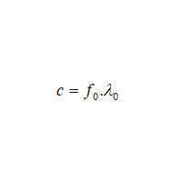
We can therefore say that the equation c = f0 · λ0
is valid for the factory settings of the device.
We place one of these devices on a tower and the other on an
airplane.
Figure
2.1 – The devices are placed on a tower and an airplane.
I can now construct the event.
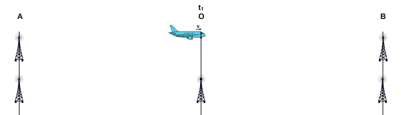
As shown in Figure 2.2, there are towers at positions A and B, and an
airplane and a tower at the central position O. For comparison, two
events are shown one beneath the other in the figure. The upper event
takes place between tower-airplane-tower, and the lower event between
tower-tower-tower. To define the airplane's position clearly, we will
take its cockpit as the reference.
The towers at positions A and B
on either side are equidistant from position O. At position O are the
signal tower on which we placed the signal-generating device and the
airplane passing through point O at that moment. We take the airplane's
speed to be constant and equal to “v.”
At this exact moment, the airplane
and tower at position O begin sending signals to the towers on either
side. I define the moment when the signals begin to be transmitted as
“t1” (Figure 2.2).
Figure 2.2 – The tower at position O and the airplane at
position O at that moment begin sending signals to the towers on either side.
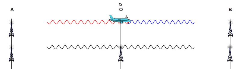
While the airplane and tower
transmit signals continuously, the airplane continues on its path
(Figure 2.3). The transmitted signals have not yet reached the towers.
Figure
2.3 – Signal transmission continues. The airplane is no longer at position O; it has moved toward the tower on the right at speed v.
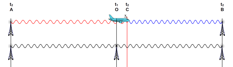
The airplane began transmitting
signals when it was at the same position as the tower at point O. The
distances OA and OB are equal. Therefore, the signals transmitted by
the airplane and the tower will reach the towers on either side at the
same time. I have defined the moment the signals arrive as “t2.”
I also denote the airplane's position at t2 by C.
Figure 2.4 – The signals transmitted by the airplane and
the central tower reach the towers on either side at the same time.
As the figures show, the event
has been described here on the basis of the “ground reference frame.”
The important question now is this: Have the events described here been
constructed correctly? More plainly, were the signals from the airplane
and tower emitted at the same time, and did they reach the side towers
at the same time? This is not a difficult question. When we examine the
event according to the ground frame, the answer is clear: Yes, it must
have occurred in this way.
The construction of the event is
therefore consistent and correct according to Classical Mechanics,
Electromagnetic Theory, and even the Theory of Relativity. Now let us
transfer Figure 2.4 to the larger Figure 2.5 below and examine the
information provided by the figure.
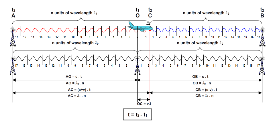
Figure
2.5 – The mathematical data produced by the figure at the moment the
signals arrive.
There are two points in the
figure above to which I particularly wish to draw your attention:
It is naturally accepted that the speed of the signals sent from
tower to tower is c. However, when we consider the airplane's reference
frame, we see that the speed of the signals transmitted by the airplane
is not c relative to the airplane.
Although the tower and airplane transmitting the signals use
identical devices, the wavelengths of the signals transmitted by the
airplane have become different. In addition, the wavelengths of the
signals transmitted by the airplane are seen to change during their
emission.
Now let us examine cases 1 and 2
mathematically in the tables below.
Table 2.1 – Calculation of signal speeds using the data
obtained from Figure 2.5
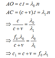
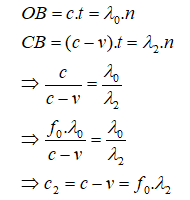
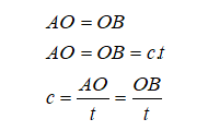
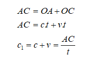
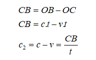
ELECTROMAGNETIC WAVE SPEED EQUATIONS Calculation of the speed of the
transmitted signal relative to the source object's own reference
frame. Figure 2.5 is used as the basis
for the calculations. Event duration: t = t2
− t1
Speed of the signal sent from the
tower to the towers at positions A and B
Source object and target object are
stationary relative to each other.
Speed of the signal sent from the
airplane to the tower at position A
Source object and target object are
moving away from each other.
Speed of the signal sent from the
airplane to the tower at position B
Source object and target object are
approaching each other.
Method 1
Method of calculating signal speed using signal wavelength and signal
frequency
Method 2
Method of calculating signal speed using time and distance
As the table shows, when we
consider the signal speeds relative to the airplane's reference frame,
we see that the speed of the signal going to tower A is “c+v” and the
speed of the signal going to tower B is “c−v.”
IT IS A LAW OF PHYSICS
“Relative to the source object's own reference frame,
the following equation holds for the speed of the signal it transmits:
Signal Speed = Frequency of the Signal It Emits × Wavelength of the
Signal It Emits”
How simple and beautiful, is it
not? In Wave Mechanics, the speed of a wave equals the product of the
wave's frequency and wavelength. We see that the same rule remains
valid even if the speed of an electromagnetic wave differs from
c. No rule is violated.
Please excuse me; believe me, it
saddens me greatly that I have to write these things, but I cannot help
saying them. Can there be a physicist who does not know this equation?
You really ought to blush a little. Unfortunately, this is truly the
situation. They have become so ill because of the Theory of Relativity
that their eyes do not see and their ears do not hear. Perhaps they are
even looking at what I have written here through clouded eyes that can
no longer see. Please heal yourselves.
As Table 2.1 again shows, we can
reach the same conclusion about signal speeds by using time and distance
values. For the speed of the signals transmitted by a source object to
be c relative to the source object's reference frame, the target object
must be stationary relative to it.
Now let us turn to the question
of where the wavelength changes.
IT IS A LAW OF PHYSICS
“If an
electromagnetic wave is traveling toward a target that is moving relative
to the source,
its wavelength changes during its emission.”
I would like to explain the
calculation used to derive this law. We had defined the time taken by
the signals to reach towers A and B as t = t2 − t1. During the signal's
travel time, the signal-generating device transmitted at frequency
f0 and emitted n sine waves.
n = f0 · t
Signals traveling to the same target will have a homogeneous structure
among themselves. Therefore, if we divide the travel distance by the
number n, we obtain the length of one wavelength. Since the airplane
transmits toward the towers at positions A and B:
AC/n = λ1 gives the wavelength of the signals traveling to tower A on
the left. CB/n = λ2 gives the wavelength of the signals traveling to tower B on
the right.
Since the wavelengths of the
signals are equal at the moments of emission and arrival, the wavelength
change occurs at the moment the signal is emitted.
What was unknown in physics was
where the change in wavelength occurred. Alice Law has thus answered
this question. The change in wavelength occurs at the moment the signal
is emitted.
Table 2.2 – Calculation of the wavelengths of the signals
transmitted by the airplane.
Method 1
Calculation of the wavelengths (λ1
and λ2) of the signals sent from the airplane to the towers
using signal frequency and distance
Calculation of the wavelength of the signal traveling from the airplane to the tower at position A:
Calculation of the wavelength of the signal traveling from the airplane to the tower at position B:
Method 2
Calculation of the wavelengths (λ1
and λ2) of the signals sent from the airplane to the towers
using signal speeds
Calculation of the wavelength of the signal traveling from the airplane to the tower at position A:
Calculation of the wavelength of the signal traveling from the airplane to the tower at position B:
Table 2.3 – Formulation of the Doppler equation
Derivation of the General Doppler Shift Equation
Using equations [1] and [2] in
Table 2.2, we can write a general equation for wavelength shift [3].
This is the Doppler Shift equation,
which remains valid today.
The ± sign in the expression takes
the value (+) if the source and target objects are moving away from each
other, and (−) if the source and target objects are approaching each other.
λ0 denotes the signal's
unchanged wavelength, the wavelength it would normally have.
I HAVE AN OBJECTION, I OBJECT
Let us pause here for a moment,
because voices of objection to what has been explained here must be
rising. The text below presents, briefly and clearly, the objections
that a physicist defending contemporary physics would raise. ChatGPT
wrote these objections for me. I am publishing the text it gave me here
without censoring it.
Objections from the Perspective of Contemporary Physics
The values AC,
CB, and t have been determined relative to the ground reference
frame. How can you calculate the signal's speed in the airplane's reference
frame using distance and time measured in the ground frame?
If you
are switching to the airplane's reference frame, should you not use Lorentz
transformations rather than Galilean transformations? You cannot obtain
the results c+v and c−v by adding v to or subtracting it from the
speed of light.
The signals arrive at the towers simultaneously
only in the ground reference frame. According to the Theory of
Relativity, these events are not simultaneous in the airplane's reference
frame. How can you use the same time interval t for both signals?
In the
equation n = f0 · t, f0 is the frequency of the device on the airplane,
whereas t is the duration measured in the ground reference frame. How can
you use these two values, which belong to different reference frames, in
the same equation?
In the figure, all wavelengths between the
emission and arrival points are shown as homogeneous and equal to one
another. But is this homogeneity a result obtained from the figure, or an
assumption accepted when the figure was constructed? Without separately
showing that the wavelengths do not change along the path, can it be said
that the change definitely occurs at the moment of emission?
In the
event you constructed, the source is moving while the targets are
stationary. How can you proceed from this to a general Doppler Shift
equation that covers every case in which the target is moving?
In response to questions of this
kind, I wish to say this: Alice Law eliminates the fundamental logic on
which the Theory of Relativity rests and brings that theory to an end.
Therefore, you cannot corner Alice Law by using the assumptions of the
theory it opposes.
Figure 2.5 uses geometry and
mathematics to show the situation that arises in the event we are
considering. If you object, what you must do is demonstrate an error in
the geometry or mathematics of Figure 2.5. You must prove that the signal
speeds relative to the airplane's reference frame are not “c+v” and
“c−v”; in other words, that the speeds of the signals transmitted by
the airplane are “c” relative to the airplane's reference frame. If
you have an objection concerning where the wavelength changes, you must
also provide a clear and definite answer on that matter.
Now you will say, “But... but...
time dilation... length contraction... these exist...” For now, I ask
you to set them aside. I ask you to forget for a while the concepts that
the Theory of Relativity has imposed on you and to open a window in your
mind. Let Alice's light reach you through it. Afterward, you will in any
case be alone with yourself and will think. Then you may exercise your
own judgment as you wish.
I must now introduce the subject of physical principles. After that, I will move on to the second part of Alice Theory. In the second part, I will also have answered the questions above.

 I will explain the hypotheses
on which Alice Law rests by constructing an event that may be considered
simple. I want us to share the same understanding of the setup,
development, and results of the event. If I can achieve this, I will
have made your transition to Alice Law easier.
I will explain the hypotheses
on which Alice Law rests by constructing an event that may be considered
simple. I want us to share the same understanding of the setup,
development, and results of the event. If I can achieve this, I will
have made your transition to Alice Law easier.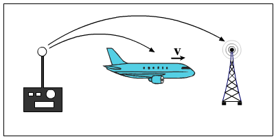


![AO/AC = c·t/((c+v)·t) = λ₀·n/(λ₁·n); c/(c+v) = λ₀/λ₁; λ₁ = λ₀·(c+v)/c [1]](../images/en/page_2/table_image_2_2_3.png)
![BO/BC = c·t/((c−v)·t) = λ₀·n/(λ₂·n); c/(c−v) = λ₀/λ₂; λ₂ = λ₀·(c−v)/c [2]](../images/en/page_2/table_image_2_2_4.png)
![λₓ = λ₀·(c±v)/c [3]](../images/en/page_2/table_image_2_3_1.png)